5 Simple Steps to Graph a Modified Goodman Diagram in Excel

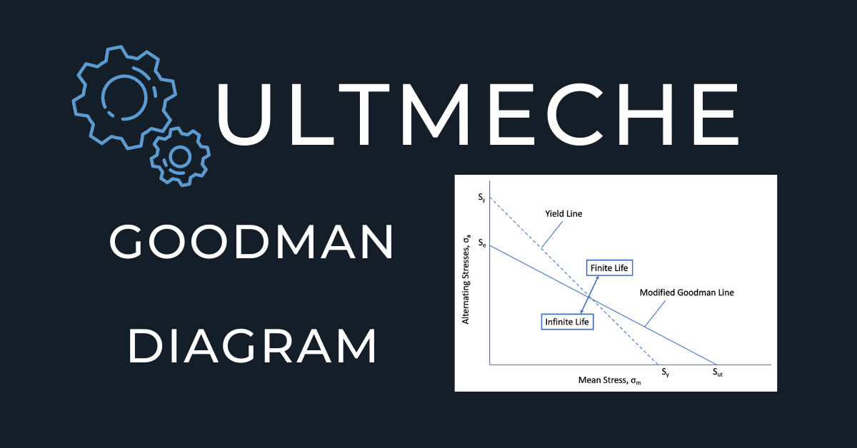
One of the key aspects of mechanical engineering and material science is understanding the endurance limits of materials under different stress conditions. The Modified Goodman Diagram is an essential tool for engineers to predict the fatigue life of components subjected to cyclic loading. In this blog post, we'll walk you through five simple steps to graph a Modified Goodman Diagram using Microsoft Excel, ensuring you can effectively analyze and predict material behavior under stress.
Step 1: Gather Your Data
Before you start plotting, ensure you have the necessary data. Here’s what you’ll need:
- Ultimate Tensile Strength (UTS): The maximum stress a material can withstand while being stretched or pulled.
- Fatigue Strength (FS): The stress level below which a material can endure infinite cycles without failing.
- Stress Cycles (σ_a) and Mean Stress (σ_m): Data from experiments or theoretical calculations detailing cyclic and mean stresses.
- Se/Fatigue Limit Ratio (Se/Sut): Ratio between fatigue strength and ultimate tensile strength.
🔍 Note: If you lack experimental data, you can often find these values in material properties databases or from literature specific to the material you are analyzing.
Step 2: Setting Up Your Excel Worksheet
Open Excel and set up your worksheet as follows:
- Label columns A to D as: σ_m, σ_a, UTS, and Fatigue Limit Ratio.
- Enter your data from Step 1 into the respective columns. The mean stress and alternating stress should have multiple entries to plot the curve accurately.

| σ_m | σ_a | UTS | Fatigue Limit Ratio |
|---|---|---|---|
| 0 | 100 | 450 | 0.55 |
Now, calculate additional data points for stress amplitude and mean stress to get a good distribution for plotting.
Step 3: Plotting the Data
With your data arranged, it’s time to create the Modified Goodman Diagram:
- Select your data range including headers (A1:D[last row]).
- Navigate to Insert > Chart > Scatter Plot.
- Choose the scatter plot with only markers (not lines).
This scatter plot will now display your points on a graph where the Y-axis represents σ_a and the X-axis σ_m.
Step 4: Drawing the Goodman Line
The Modified Goodman Diagram plots a line that separates the safe region from the failure region. Here’s how to plot this line:
- Select your scatter plot, then go to Chart Design > Add Chart Element > Trendline.
- Choose Linear for the trendline type.
- Adjust the formula to meet the Goodman criteria:
- Slope = -Se/Sut
- Intercept = Se
Step 5: Enhancing Your Diagram
Now that you have the basic plot, let’s make it more informative and visually appealing:
- Add Axis Labels: Label the X-axis as “Mean Stress (σ_m)” and Y-axis as “Alternating Stress (σ_a)”.
- Legend: Add a legend to distinguish between data points and the Goodman line.
- Formatting: Adjust the scale to ensure all your data points are visible. Enhance with colors, marker styles, and line weights for clarity.
Your Modified Goodman Diagram should now look complete and ready for analysis, providing a visual representation of safe and failure zones under different stress conditions.
💡 Note: Remember that this diagram assumes linear material behavior and does not account for factors like surface finish, temperature, or stress concentration, which can affect the fatigue life significantly.
To summarize, constructing a Modified Goodman Diagram in Excel involves careful data collection, setting up the spreadsheet correctly, plotting the data accurately, and then enhancing the visual presentation for better understanding. This tool is invaluable in designing components that will endure repetitive stresses over time, ensuring reliability and safety in mechanical engineering applications.
What is the purpose of a Modified Goodman Diagram?
+The purpose of a Modified Goodman Diagram is to provide a visual tool to predict the fatigue life of materials under cyclic loading. It helps engineers determine safe and failure zones based on mean stress and alternating stress, aiding in the design of components to withstand repetitive stresses.
How do I interpret the Modified Goodman Diagram?
+Any stress combination (σ_m, σ_a) below the Goodman line indicates that the material can withstand infinite cycles without failure. Above this line, failure is predicted, indicating you need to reconsider the design or material selection.
Can I use this method for any material?
+The Modified Goodman Diagram is primarily used for ductile materials. For brittle materials, other methods like the Soderberg line might be more appropriate, as they take into account the yield strength instead of UTS.


